
Major home appliance manufacturers are always adding new
features and simplifying the use of their products in order to maintain a
competitive edge. New designs also are influenced by current and pending
government regulations on energy efficiency and water usage. In many major
appliances, advanced three-phase variable speed drive systems provide the
performance improvements needed to meet these demands.
Designing
fractional horsepower drives for home appliances such as refrigerators and
washing machines presents some interesting technical challenges. As a result,
manufacturers are turning to a digital-signal processing (DSP) control
platform. The following applications show how DSP motor control designs are
implemented in two different home appliances.
Home Refrigerator Control
A home refrigerator runs continuously and, therefore, consumes a significant
amount of electricity. Since the main power consuming element is the
compressor, appliance manufacturers are always looking to improve its cooling
efficiency.
Designers
can boost efficiency by reducing the speed of the compressor to match the
cooling required for normal refrigeration operation. High-speed operation is
reserved only for rapid cooling whenever the refrigerator is filled with food.
The more simple control methods for single-phase induction motors result in a
significant loss in efficiency of the motor. For fractional horsepower
applications, the motor with the highest efficiency is an electronically
controlled three-phase permanent magnet motor.
In
domestic refrigeration systems, the compressor and motor are hermetically
sealed within the same metal enclosure. The environment within the chamber is
quite harsh, so Hall sensors can't be used. These sensors are typically used in
other low-cost permanent magnet drives. As a result, a sensorless mode of
operation where the motor acts as its own commutation sensor is essential.
Consequently,
the target for a refrigeration application is to provide a drive for a 200-W
compressor motor, without sensors, at minimum size and cost, and meeting all
the regulatory requirements for electromagnetic compatibility (EMC) and safety.
Motor Control Strategy
A permanent-magnet motor is the most efficient ac motor type. It doesn't
require rotor magnetizing current as does an induction motor. However, to run
an ac motor efficiently, it is important to synchronize the frequency of the
applied voltage with the position of the permanent-magnet rotor.An effective
control scheme is to run the motor in a six-step commutation mode with only two
windings active at any one time. In this case, the back emf on the unconnected
winding is a direct indication of the rotor position. This position is
estimated by matching a set of back emf waveform samples to the correct segment
of the stored waveform profile. This technique averages the data from a large
number of samples giving a high degree of noise immunity.
The
control system has an inner position control loop . This adjusts the angle (qs)
of the applied stator field to keep the rotor synchronized. The integrator
input tracks the motor velocity when the rotor position error is forced to
zero. The outer velocity loop adjusts the applied stator voltage magnitude to
maintain the required velocity. The controller can accelerate the compressor to
its target speed within a few seconds and can regulate speed to within 1% of
its target. The smooth running of the compressor reduces audible noise. The
lower operating speed helps minimize the temperature cycles in the
refrigeration compartment, and improves the quality of food refrigeration.
The complete drive system includes the EMI filter, the input rectifier, the
control power supply, the DSP motor control circuit, the signal conditioning
circuits, the power inverter, and gate drives .
ADC Checks Currents, Voltages
Upon power-up, the internal program RAM inside the controller IC is loaded from
an 8-pin external boot ROM via one of the serial ports. The control program
performs initialization and diagnostics and then starts the motor in an
open-loop mode. When the back emf reaches a minimum level, the motor is
switched to normal running mode. During every PWM cycle the analog-to-digital
converter (ADC) samples the motor back emf, the motor current, and the bus
voltage.
An
internal multiplexer selects the appropriate back emf signal to be converted.
The DSP CPU calculates a new rotor position estimate and calculates the PWM
duty cycle needed to apply the required voltage to the motor. At particular
values of estimated rotor position angle, the CPU selects a new set of active
motor windings by writing to the PWM segment selection register. The CPU also
performs diagnostic functions and monitors dc bus voltage, motor current, and
speed. In the case of overload conditions, the drive is shut down and a restart
is attempted after a short time delay.
The
drive power stage consists of a full three-phase MOSFET power inverter bridge
and three integrated gate drive amplifiers. The rectifier common is connected
to the control IC ground; so the PWM outputs are connected directly to the gate
drive inputs. The back emf signal conditioning consists of three matched
high-voltage resistive dividers and a passive RC filter. The current amplifier
circuit is synchronized to the PWM sampling frequency in a way that it can
determine the motor winding current from the dc bus current.
To reach the cost targets demanded by this application, the complete control
hardware, including the processor core, memory, PWM, and ADC, was integrated
into a single motor control IC. The ADMC330 DSP motor controller is an example
of a single-chip DSP device for this application. It has three independent
computational units within the CPU section: an arithmetic logic unit (ALU), a
multiply and accumulate unit (MAC), and a shifter unit.
The memory-mapped
PWM controller requires only three register writes per PWM cycle to control the
motor winding voltages. This minimizes the processor overhead in generating PWM
signals. The ADC is synchronized to the PWM frequency, producing four updated
samples every PWM cycle.
The
other elements of the drive solution include the control power supply and the
EMC components to meet all the regulatory requirements. The compact power
supply design derives the +15 V and +5 V supplies from the 300-V supply using a
two-stage buck converter, thus avoiding the use of a bulky ac line transformer.
The
complete motor drive system is integrated onto a single control card . The major challenges were in minimization of
the control board size and manufacturing costs. The minimum size constraint on
the board meant that the DSP motor control IC was placed within 2 inches of a
MOSFET power inverter switching currents greater than 1A from a 300-V bus. For
this reason, special attention was placed on the power circuit layout, routing,
and grounding in order to prevent any inverter switching noise from coupling
into the control circuits. All the high-current-carrying components and tracks
are close to the ac power and motor connectors.
Also
included are the external components needed to run the IC. These are the
power-on reset IC (R), the clock crystal (XT), the boot ROM (M), and an ADC
capacitor. The final drive product met the customer cost targets and delivered
in a 30% reduction in energy consumption by the compressor compared to a
fixed-speed, single-phase motor.
Washing Machine Control
European and Japanese washers are typically horizontal axis machines
with a drum driven by a universal brush type motor. Drum speed control can be
implemented using a phase controlled rectifier and an 8- or 16-bit
microcontroller. However, universal motors have well-known problems of brush
wear and limitations on their high-speed range. In contrast, ac induction motors
don't use brushes and have a wider speed range.
In this
application, the speed ripple and load torque of the washing machine motor
provide valuable information on the washing load. The load torque variation
with the drum rotation can provide information about the predominant fabric in
the wash load. Thus, the machine controller can automatically select the wash
program and simplify the use of the machine. The speed ripple can be used to
estimate the load unbalance before starting the spin cycle, thereby improving
the mechanical reliability of the machine.
Motor Control Strategy
The control of an ac induction motor (ACIM) is potentially much
simpler than that required for a permanent-magnet ac motor. Driven in open-loop
configuration by a three-phase inverter, the ACIM offers adequate speed-control
for many simple pump and fan applications.
However,
when a wide speed range and high dynamic performance is required, a
field-oriented control scheme is necessary. In this case, the flux- and torque
currents are independently controlled to provide a performance similar to that
obtainable from a permanent magnet synchronous motor. In the low-speed range of
operation the flux is kept constant and torque is directly proportional to the
torque current. In the high-speed range, when the motor voltages are limited by
the dc bus voltage, the flux is reduced to allow operation at higher speeds.
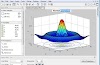
Shown
is a direct stator field-oriented control scheme (Fig. 4). The key motor variables are the flux and
torque-producing components of the motor currents. The choice of reference
frame is the key element that distinguishes the various vector control
approaches from one another. In this scheme, a reference frame synchronized to
the rotating stator flux is selected because of the availability of stator
current and dc bus voltage information. A number of other field-oriented
schemes require position information or stator flux measurements. These are not
suitable for this application where controlled operation at close to zero speed
is not required.
The
Park and Clark reference-frame transformation functions calculate the effect of
the stator currents and voltages in a reference frame synchronized to the rotating
stator field. This transforms the stator winding currents into two quasi dc
currents representing the torque producing (Iqs) and flux producing (Ids)
components of the stator current.
The
stator flux angle is an essential input for the reference-frame transformations.
The stator flux is calculated in the fixed reference frame by integrating the
stator winding voltages. In this system, the stator voltage demands to the
inverter are known. Therefore, the applied stator voltages can be calculated
from the voltage demands and the dc bus voltage measurement. The flux
estimation block uses stator current to compensate for the winding resistance
drop. The outputs of this block are the stator flux magnitude and the stator
flux angle.
There
are four closed control loops in this application. Two inner current loops
calculate the direct and quadrature stator voltages required to force the
desired torque and flux currents. The Park and Clark functions transform these
voltages to three ac stator voltage demands in the fixed reference frame. The
outer loops are the speed and flux control loops. The flux demand is set to
rated flux for below base-speed operation. It is reduced inversely with speed
for above base- speed operation in the "field weakening mode."
Finally, the torque loop is the same as in any classical motion control system.
Induction Motor Control
The hardware portion of the ac induction motor system is implemented using the
same generic variable speed ac drive configuration as the permanent-magnet
drive described earlier. In this case, the motor is rated at over 400 W, so
IGBT's are the power devices most suited to the application. The feedback
signals include the motor currents, the bus voltage and a pulse train from a
digital tachometer. The motor winding current is derived from the power
inverter currents. The DSP motor controller calculates velocity by timing the
pulse-train frequency from the digital tachometer.
The DSP
motor control IC communicates with the front-panel washing machine control over
an isolated serial link. This allows speed profile information to be downloaded
to the controller, and motor speed and torque information to be uploaded to the
washing machine controller.
The
control software for the washing machine application was developed for an
ADMC331 motor control IC. The challenge for this controller was to run four
simultaneous control loops where the variables have a very wide dynamic range.
A solution, which very much improved performance, was to use floating point
variables for all the PI control loops. This extended the processing time
somewhat but was not found to be a significant burden when using a 25 MIPS DSP
core.
The
processor must handle multiple interrupt sources from the ADC, the digital I/O
block, the communication ports, and the timer. A number of useful device
features such as an autobuffered serial port and a single context switch made
the task possible without significant overhead in pushing or popping a stack.
Finally, the code development was somewhat simplified by the availability of
library functions on the ADMC331 ROM for mathematical functions and the Park
and Clark transformations.
The
availability of DSP microcontrollers presents a new set of challenges for
motor-control design engineers. The vast increase in processing power over
standard microcontrollers offers an opportunity to increase drive performance
or reduce cost. The two examples given here show that to fully employ this
power requires new control approaches and philosophy. The challenge will be to
fully exploit the opportunities possible with this new technology. The world of
domestic appliances is changing in a similar fashion as the automotive industry
changed a few years ago. The future is a world of "intelligent" home
appliances.


0 Comments