DTC is “Direct Torque Control,” a method used by ABB in their high-performance drives. “Vector” control is a generic term, while “DTC” is specific in how the “vector control” is performed.
Essentially, there are two components of current in the stator of an induction motor. One part provides the magnetic field flux, and that component is phase-shifted 90° from the applied voltage. The other component of current provides the shaft torque - the actual power output of the motor and is (by definition) in phase with the applied voltage. The vector sum of these two currents gives the measured motor current amplitude and phase angle (power factor) of the motor current.
The portion of current that provides the field flux is pretty much a constant so long as the voltage/frequency relationship is maintained in a linear fashion - that is, so long as the applied voltage at 50% frequency (for example) is 50% of that applied at 100% frequency. The inductive reactance, resistance, capacitive reactance, etc. of the motor are fixed by the motor’s construction. One thing almost all vector VFDs require when being commissioned is an “autotune” run while connected to the motor. At a minimum, this autotune function detects the motor constants necessary for modeling the electrical behavior of your motor. It may also include spinning the shaft and performing stepped speed changes to detect rotor inertia and back EMF, but at a minimum the motor’s resistance, impedance, etc. will be recorded.
It is critical that the motor nameplate information (full load amps, full load speed at base frequency, voltage rating) be entered into the VFD programming correctly, or the model will not be accurate.
Once this information has been gathered, the VFD can then determine how much current is being consumed to produce torque, and can do so with significant precision even without a shaft position sensor.
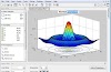
The six output transistors have a total of six switching positions that will result in current flow in the stator and thus torque in the motor shaft. See this image:

By comparing the load current to these six torque vectors, the VFD can “decide” when the transistors need to be switched to provide the optimal torque vector, and how much voltage needs to be applied to the stator to produce the torque necessary.
The difference between standard PWM vector switching and DTC vector switching is that in a PWM system, the number of pulses per second is fixed (termed “carrier frequency”) and therefore the absolute speed at which the vector model can be implemented is somewhat limited. Plus, all of this is determined by the accuracy and sampling rate of the current transducers being used on the output of the VFD.
ABB’s system uses highly accurate current sensors that are monitored at a very high rate (20k samples per second, if I recall correctly), and the DTC model does not use a “carrier frequency” - the transistors are switched strictly on the needs of the motor model. At steady speed and load the output looks very much like a standard PWM waveform, but in dynamic applications it does not.
Vector is very good at providing precision speed control without speed- or shaft-position feedback, and in addition it tends to provide the best torque-per-amp performance available, but starting torque is a slightly different topic.
Here is the speed torque curve of a standard (Design B) induction motor started with full voltage/frequency (across-the-line start):

The NEMA standard for a Design B motor sets the minimum limits for locked rotor torque (zero speed), pull-up torque, and breakdown torque. However, this isn’t to say that a manufacturer’s particular motor cannot exceed these limits. But when operating on a VFD, the motor never operates at more than a few percent slip - that is, it operates on the side of this curve from the breakdown torque to no-load, and that curve shifts left and right with the applied frequency, thus:

Note on this diagram that the breakdown torque at 6Hz is considerably lower than it is at 30Hz or even 10Hz. As the output frequency of the VFD approaches zero, it (by definition) begins to behave more and more like DC. What a vector drive gets you is better starting torque because it has that motor model, and it can automatically alter the output voltage to produce the maximum amount of starting torque.
When operating on that right side of the speed/torque curve, the motor current is pretty linear with the load (neglecting the excitation component for a moment). For example, let’s say we have a 1490RPM 50Hz motor. The slip is 10RPM at 100% load. The equation for synchronous speed is 120F/P where F is applied frequency and P is the number of poles. Ours is a 4 pole motor, since 120(50)/4 = 1500. Then 10RPM represents 0.33Hz. At 6Hz the motor would be spinning 170RPM at full load. If the drive is capable of delivering MORE than full load current (and it had better be) at least for a short time, then it should be capable of providing more than full load torque - up to the capacity of the motor to make torque and the limits of the output current of your VFD. The capacity of the motor to make torque is strictly a function of how the manufacturer designed it, and all motors are not equal. The limits of the output current of your VFD is a function of how the manufacturer designed it, and again, all VFDs are not equal.
Compare the full load amps on the motor nameplate with the overload capacity of your VFD for a baseline idea of just how much torque you might be able to get out of your motor during start. Here’s a Siemens motor nameplate:

The motor is rated 30Hp at 34.9A at 1765RPM and 460V. It’s a NEMA Design B, so its locked-rotor torque rating is (at minimum) 150% of its rated torque. What’s its rated torque? That’s not on the nameplate, is it? There’s an equation, though. Torque (in ft.lbs) is (Hp x 5252)/RPM. Our motor is 30Hp and its rated speed is 1765RPM, so it is rated for 89.27 ft.lbs. at 34.9 amps. Its minimum locked rotor torque rating is 134 ft.lbs.
ABB ACS800 Direct Torque Control 460V VFDs are rated by their continuous current and overload capacity. The closest ABB offers to a 34.9A rating is the ACS800–01–0030–5, rated 42A continuous, but it’s “light overload” continuous current rating is 39.0A. Let’s select that one. The catalog for this drive says it can produce 62A for 10 seconds at start, and 42.9A for 60 seconds. 62A is 177% of the motor’s full load rating. If I were applying this drive in it’s “Scalar” or Volts/Hz mode (or anybody else’s VFD that is not a vector drive), then my rule of thumb is to assume that I can only get about 80% of that torque. If the motor’s full load torque is 89.27 ft.lbs, then 177% of that is 158 ft.lbs, and 80% of THAT is 126 ft.lbs.
That’s well over full load torque, but it isn’t locked-rotor torque. But because this is an ABB drive with DTC (or anybody’s good vector VFD with a good tune), I’m going to assume I can get about 90% of that max torque. 90% of 158ft.lbs is 142 ft.lbs, and that’s more than locked-rotor torque. But it can only sustain that for 10 seconds. If you can’t get the load spinning with that, then the motor will probably stall when the 10 seconds are up. If you need to produce that torque for longer than 10 seconds, you need a drive that can give it to you for longer.
In VFD applications, torque is everything. What is your worst-case torque and at what speed? Usually it’s starting, but not always. Current is torque. Voltage is the ability to make torque. Another rule of thumb: If you can start the load with the motor you have and a full-voltage starter, then you can put a VFD on it that will start it, too - it just might not have a nameplate that matches the motor. Your 30Hp (22kW) motor might need a 40Hp (30kW) VFD to get it started.


0 Comments