
Electricity is the most versatile and
widely used form of energy. The global demand for electricity is continuously
growing. Of the total generation worldwide, more than 60 per cent of energy is
generated using coal-fired station resulting in carbon dioxide emission
threatening the global warming. To mitigate the consequence of climate change,
generation systems need to undergo significant changes.
One of the major issues in power
system is the losses occurring during the Transmission and Distribution
(T&D) of electrical power. The percentage of loss of power during T&D
is approximated as 26 per cent. The main reason for power loss during T&D
is the resistance of wires used in grid. According to the World Resources
Institute (WRI), India’s electricity grid has the highest T&D losses in the
world – a whopping 27-40 per cent. Tesla had proposed methods of transmission
of electricity using electromagnetic induction.
Tesla had always tried to introduce
worldwide wireless power distribution system. But due to lack of funding and
technology of that time, he was not able to complete the task. Research is
being going on and recent developments have been observed in this field.
Despite advances, wireless power transmission has not been adopted for
commercial use.
In 1899 Sir Nicolas Tesla and
Heinrich Hertz powered a fluorescent lamp keeping it 25 miles away from source.
Wireless power transmission experiments were conducted at Warden Clyffe tower.
High frequency current, of a Tesla coil, could light lamps filled with gas
(like neon). In this method, a closed circuit is made using transmitter,
ionized path between upper atmosphere and transmitter, second ionized path
connecting receiver. The circuit back to the transmitter is completed through
the earth. High potential is maintained at transmitter and receiver end as
well. A high potential transmitter transmits an electromotive impulse through
the ionized path to the upper atmosphere where it ionizes the air and this air
between the transmitter and receiver would conduct like a neon tube.
Methods of Wireless Transmission of Electrical Power
Induction
The principle of mutual induction
between two coils can be used for the transfer of electrical power without any
physical contact in between. The simplest example of how mutual induction works
is the transformer, where there is no physical contact between the primary and
the secondary coils. The transfer of energy takes place due to electromagnetic
coupling between the two coils.
Electromagnetic Transmission
Electromagnetic waves can also be
used to transfer power without wires. By converting electricity into light,
such as a laser beam, then firing this beam at a receiving target, such as a
solar cell on a small aircraft, power can be beamed to a single target. This is
generally known as “power beaming”.
Evanescent Wave Coupling
Researchers at MIT believe they have
discovered a new way to wirelessly transfer power using non-radiative
electromagnetic energy resonant tunneling. Since the electromagnetic waves
would tunnel, they would not propagate through the air to be absorbed or
wasted, and would not disrupt electronic devices or cause physical injury like
microwave or radio transmission. Researchers anticipate up to 5 meters of
range.
Electrodynamic Induction
Also, known as “resonant inductive
coupling” resolves the main problem associated with non-resonant inductive
coupling for wireless energy transfer; specifically, the dependence of
efficiency on transmission distance. When resonant coupling is used, the
transmitter and receiver inductors are tuned to a mutual frequency and the
drive current is modified from a sinusoidal to a non-sinusoidal transient
waveform. Pulse power transfer occurs over multiple cycles. In this way,
significant power may be transmitted over a distance of up to a few times the
size of the transmitter.
Radio and Microwave
Power transmission through radio
waves can be made more directional, allowing longer distance power beaming with
shorter wavelengths of electromagnetic radiation, typically, in the microwave
range. A rectenna may be used to convert the microwave energy back into
electricity. Rectenna conversion efficiencies exceeding 95% have been realized.
Power beaming using microwaves has been proposed for the transmission of energy
from orbiting solar power satellites to Earth and the beaming of power to
spacecraft leaving orbit has been considered.
Electrostatic Induction
Also, known as ‘capacitive coupling’
is an electric field gradient or differential capacitance between two elevated
electrodes over a conducting ground plane for wireless energy transmission
involving high frequency alternating current potential differences transmitted
between two plates or nodes.
Current Technology in the Field Of Wireless Power Transmission
Microwave Transmitter
The most current research and
proposals use microwaves as the frequency range of choice for transmission. At
present an efficiency of 76 per cent is possible using current technology for
microwave power transmission. For transmission efficiency, the waves must be
focused so that all the energy transmitted by the source is incident on the
wave collection device. Higher frequencies are also impractical because of the
high cost of transmitters and the relative low efficiency of current optical
and infrared devices.
The most common transmitters for
microwaves are the travelling wave tube (TWT), klystron and magnetron. The TWT
is far too expensive and power restrictive making it impractical for the task
of power transmission. The klystron has been the DC to microwave converter of
choice however it is also somewhat expensive. Many researchers are looking to
use magnetrons instead because they are cheap and efficient. Magnetron
frequency output is not as precisely controllable as the klystron or TWT but
power transmission is more lenient to frequency fluctuations than communication
systems are. One of the more common proposals would be for an array of
magnetrons to be used as the transmitter. One of the main advantages to using
many smaller magnetrons as opposed to a few klystrons is that 300 W to 1kW
magnetrons are already mass produced for microwave ovens. The efficiency of
magnetrons is inconsistently reported.
Use of Microwave Power Transmission in Solar Power Satellites (SPS)
Solar power generating satellites
launched into space and transmitting power to Earth stations. This idea was
first proposed in 1968 and all of the experiments have only been carried out in
terrestrial laboratories. The SPS satellites would be put in high earth orbit
at geosynchronous location. This would allow them to receive light 99 per cent
of the year. A large rectenna array facility will be built on the Earth to
collect the incoming microwaves. To maintain a good lock on the rectenna, the
satellite will need to be built with a retro directive transmitter which locks
on to a pilot beam emanated from the ground station.
Since most of the research is done in
the 2.4 GHz to 5.8 GHz range, there is some spectrum regulatory issues to deal
with. Also since the retro directive antenna system is unproven, there is the
health concern that the microwave beam could veer off target and microwave some
unsuspecting family. However, a Japanese Government agency is planning to send
up 10 to 100 kW low earth orbit satellite to prove its feasibility.
Latest Invention & Experiments
WiTricity
The new technology called WiTricity
is based on using coupled resonant objects. Two resonant objects of the same
resonant frequency tend to exchange energy efficiently, while interacting
weakly with extraneous off- resonant objects. After Nicolas Tesla, there was
rebirth of this in 2007 by the team from Massachusetts Institute of Technology,
who call their invention ‘WiTricity’. In the first successful trial of its
kind, the team was able to illuminate a 60-watt light bulb 7ft away. They
simulated a transfer of 60W across two identical loops similar in dimension.
The coils had a radius of 30 cm, with a cross section of 3cm and distance
between the coils was 200m. Basic principle is two resonant objects of the same
resonant frequency tend to exchange energy efficiently, while interacting
weakly with extraneous off-resonant object
The investigated design consists of
two copper coils, each a self-resonant system. One of the coils, attached to
the power source, is the sending unit. The resonant nature of the process
ensures the strong interaction between the sending unit and the receiving unit,
while the interaction with the rest of the environment is weak.
Solar Power Satellite
Future suitable and largest
application of the WPT via microwave is a Space Solar Power Satellite (SPS).
The SPS is a gigantic satellite designed as an electric power plant orbiting in
the Geostationary Earth Orbit (GEO). It consists of three segments solar energy
collector to convert the solar energy into DC (direct current) electricity,
DC-to-microwave converter, and large antenna array to beam down the microwave
power to the ground. The first solar collector can be either photovoltaic cells
or solar thermal turbine. The second DC-to-microwave converter of the SPS can
be either microwave tube system or semiconductor system. It may be their
combination. The third segment is a gigantic antenna array.
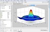
An amplitude taper on the
transmitting antenna is adopted in order to increase the beam collection
efficiency and to decrease sidelobe level in almost all SPS design. A typical
amplitude taper is called 10 dB Gaussian in which the power density in the
center of the transmitting antenna is ten times larger than that on the edge of
the transmitting antenna.
The SPS is expected to realise around
2030. Before the realisation of the SPS, we can consider the other application
of the WPT. In recent years, mobile devices advance quickly and require
decreasing power consumption. It means that we can use the diffused weak
microwave power as a power source of the mobile devices with low power
consumption such as RF-ID. The RF-ID is a radio IC- tug with wireless power
transmission and wireless information. This is a new WPT application like
broadcasting.
Antennas for Microwave Power
Transmission
All antennas can be applied for both
the MPT system and communication system, for example, Yagi-Uda antenna, horn
antenna, parabolic antenna, microstrip antenna, phased array antenna or any
other type of antenna. To fixed target of the MPT system, usually large
parabolic antenna selected in MPT demonstration in 1975 at the Venus Site of
JPL Goldstone Facility and inground-to-ground MPT experiment in 1994-95 in
Japan. In the fuel-free airship light experiment with MPT in 1995 in Japan,
they changed a direction of the parabolic antenna to chase the moving airship.
However, we have to use a phased array antenna for the MPT from/to moving
transmitter or receiver which include the SPS because we have to control a
microwave beam direction accurately and speedy. Power distribution at the
transmitting antenna is given by (1-r²), where r is the radius of antenna.
The phased array is a directive
antenna which generates a beam form whose shape and direction by the relative
phases and amplitudes of the waves at the individual antenna elements. It is
possible to steer the direction of the microwave beam. The antenna elements
might be dipoles, slot antennas, or any other type of antenna, even parabolic
antennas. In some MPT experiments in Japan, the phased array antenna was
adopted to steer a direction of the microwave beam. All SPS is designed with
the phased array antenna. We consider the phased array antenna for all
following MPT system.
Japan wants to power up three million
houses with wireless energy from space. They have serious plans to send a
solar-panel-equipped satellite into space that could wirelessly beam a giga
watt-strong stream of power down to earth. A small test model is scheduled for
launch in 2015. To iron out all the kinks and get a fully functional system set
up is estimated to take three decades. A major kink, presumably, is coping with
the possible dangers when 1-gigawatt microwave beam aimed at small spot on
Earth misses its target. The $21 billion project just received major backing
from Mitsubishi and designer IHI (in addition to research teams from 14 other
countries).
Wireless Power Transmission
Components of WPT system: The Primary
components of Wireless Power Transmission are Microwave Generator, transmitting
antenna and Receiving antenna (Rectenna).
Transmission System
In the transmission side, the
microwave power source generates microwave power and the output power is
controlled by electronic control circuits. The waveguide circulator which
protects the microwave source from reflected power is connected with the
microwave power source through the coax- waveguide adaptor. The tuner matches
the impedance between the transmitting antenna and the microwave source. The
transmitting antenna radiates the power uniformly through free space to the
rectenna impedance matching is the practice of designing the input impedance
electrical load output impedance to maximise the power transfer or minimise
reflections from the load.
Magnetron
Magnetron is a crossed field tube
which forces electrons emitted from the cathode to take cyclonical path to the
anode. The magnetron is self-oscillatory device in which the anode contains a
resonant RF structure. The magnetron has long history from invention by A W
Hull in1921. The practical and efficient magnetron tube gathered world interest
only after K. Okabe Average RF output power versus frequency for various
electronic devices and semiconductors.
Conclusion
Wireless power transmission of
electrical power can be considered as a large scope in future prospects of
power generation and transfer. Solar power satellites are the future for
supplying non- conventional energy. The various methods and aspects regarding
wireless transmission of electrical power and the details of design of solar
power satellite have been discussed. The evolution of the technology from the
time of Tesla has been overviewed.


0 Comments